THz Diffraction Gratings
| Download THz Diffraction Gratings Datasheet (PDF, 778 KB) |

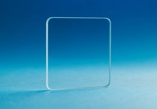
Diffraction gratings produced by Tydex are intended for spectral measurements in THz frequency range. They are relief-phase transmission gratings. Regular structure of such gratings is created by cutting parallel dashes (grooves) into a transparent substrate. The substrates are made of materials transparent in THz range, such as TPX (polymethylpentene) and ZEONEX (cyclic olefin polymer).
The gratings may be used for:
- THz spectroscopy;
- THz diagnostic instruments;
- Electro-optical devices;
- Astronomy and astrophysical applications, including space-based;
- Materials research.
The gratings are manufactured in four standard options for the following transmission bands within the 0.3-3 THz range: 0.28–0.55 THz; 0.49–0.98 THz; 0.87–1.75 THz; 1.56–3.12 THz. Gratings for other bands within 0.3-3 THz range can be manufactured at customer’s request.
The transmissivity spectra of TPX and ZEONEX plates polished on both sides before cutting the grooves are given below.
 Fig. 1. Transmissivity of 2 mm TPX plate

Fig. 2. Transmissivity of 2 mm ZEONEX plate
THz gratings are usually made square-shaped, 35 mm to 70 mm on a side. Other shapes and sizes are available on demand.
Depending on the intended application, diffraction gratings can be used in various optical arrangements, with or without converging lenses.
Gratings parameters, diffracted wave intensities and first-order maxima angles for individual monochromatic waves are calculated using Fraunhofer approximation.
To validate the operation and compare calculated and actual parameters, characteristics of the gratings were measured in various optical arrangements with different terahertz radiation sources. Two sources were used. The first was FIR-laser, a submillimeter methanol-vapor laser optically pumped by tunable CO2 laser (Peter the Great St. Petersburg Polytechnic University). The second was FEL, a free-electron laser (Siberian Synchrotron and THz Radiation Center, Budker Institute of Nuclear Physics, RAS). Figures 3 and 4 depict monochromatic wave intensity (λ=118 μm) versus diffraction angle for TPX and ZEONEX gratings with spacing d=250 μm, when FIR-laser was used as a radiation source. Figures 5 and 6 give monochromatic wave intensity (λ=141 μm) versus diffraction angle for the same gratings illuminated by FEL. In the second case a converging lens was placed between the grating and radiation sensor. Comparison of these plots shows that in the first case zero- and first-order maxima are wider than with lens arrangement. This is due to focusing parallel beams by the converging lens. It must be taken into account by the users when designing the experiments according to their intent. When the grating is used to study the properties of the radiation source (power, beam shape, energy distribution etc.), a lens is redundant. But when spectral lines need to be resolved, the lens becomes necessary.
For a diffraction grating with a specific transmission band determined using the Rayleigh criterion, the diffracted monochromatic wave intensity is wavelength-dependent. It reaches the maximum in the middle of the range and falls off near its borders. For example, figures 3-6 show that for TPX and ZEONEX diffraction gratings with 250 μm spacing (transmission band 1.56-3.12 THz, or 96-192 μm) the first-order maxima intensity for a λ=141 μm monochromatic wave is several times greater than for λ=118 μm monochromatic wave. (First one is in the middle of the transmission band, whereas second one is closer to the edge.) It matches to the theoretical diffracted wave intensities and first-order maxima angles for individual monochromatic waves calculated using Fraunhofer approximation. Due to different radiation sources and optical arrangements used when testing the gratings, intensity below is given in arbitrary units.

Fig. 3. Diffracted monochromatic wave intensity (λ=118 μm) versus diffraction angle for TPX gratings with spacing d=250 μm. Radiation source: FIR-laser. Signal was measured without a converging lens.

Fig. 4. Diffracted monochromatic wave intensity (λ=118 μm) versus diffraction angle for ZEONEX gratings with spacing d=250 μm. Radiation source: FIR-laser. Signal was measured without a converging lens.

Fig. 5. Diffracted monochromatic wave intensity (λ=141 μm) versus diffraction angle for TPX gratings with spacing d=250 μm. Radiation source: FEL. Signal was measured with a converging TPX lens.

Fig. 6. Diffracted monochromatic wave intensity (λ=141 μm) versus diffraction angle for ZEONEX gratings with spacing d=250 μm. Radiation source: FEL. Signal was measured with a converging TPX lens.
The study data for the relief-phase terahertz gratings shows their high optical efficiency and resolution of the operational maxima. Thus, such gratings can be efficiently used to study the spectra of radiation sources, including low-power sources, which is an important capability for studies in the THz frequency range.
For price quotation and delivery please fill in our Request form.
Optics is ready to be shipped!
Optics Stock
Shipment/ Payment/ Warranty ...